
Have you ever seen a bar twist under load and wondered why some parts barely move while others spin easily? That difference comes down to torsional stiffness.
Torsional stiffness is the ratio of applied torque to the resulting angular twist in a structural element. For a shaft, it can be expressed as (K_t = \dfrac{T}{\theta}), where (T) is torque and (\theta) is twist angle in radians.
In the rest of this article I will walk you through why torsional stiffness matters in design, how engineers measure and improve it, and what the latest trends are. Let’s dive in.
Why is torsional stiffness important in design?
Imagine a long drive shaft in a car or a beam in a building twisting when it should stay firm. That’s the problem torsional stiffness helps prevent.
Torsional stiffness ensures structural components resist twisting under torque, protecting alignment, performance, and longevity.
When I design components — whether for industrial machinery or structural systems — I always ask: “How much twist can this take before it causes misalignment, vibration, or failure?” Torsional stiffness answers that.
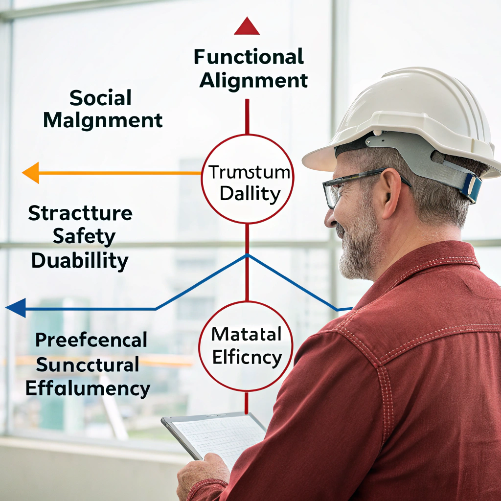
Key reasons it matters
- Functional alignment and performance
- Structural integrity
- Safety and durability
- Weight and material efficiency
How torsional stiffness fits into design parameters
| Parameter | Effect on torsional stiffness |
|---|---|
| Shear modulus (G) | Higher G → higher stiffness |
| Cross‑section geometry | Larger polar moment of inertia (J) → higher stiffness |
| Length (L) | Longer length → lower stiffness |
| Material defects/joints | Joints or weak spots reduce effective stiffness |
In many machine‑design cases, I treat torsional stiffness as one of the core stiffnesses (axial, bending, torsional) that determine how the part will behave under load. Ensuring that torsional deflection stays within acceptable limits is essential for performance, durability, and user satisfaction.
How to measure and improve torsional stiffness?

You might know the concept, but how do you put a number on it? And once you do, how do you raise that number without blowing the budget?
You measure torsional stiffness by applying a known torque and measuring the corresponding twist angle, or calculating via (K_t = G \cdot \dfrac{J}{L}).
When I measure torsional stiffness in practice I follow these steps:
- Define test conditions
- Apply torque and measure angle
- Calculate stiffness using formula
- Use sensors or FEA if needed
How to improve torsional stiffness
Geometry changes
- Increase shaft diameter
- Use hollow tubes with large outer radius
- Shorten effective length
Material and design choices
- Use higher shear modulus material
- Add stiffening ribs or closed sections
Manufacturing and assembly
- Avoid loose joints
- Use precise machining
- Proper support and alignment
Real-world example
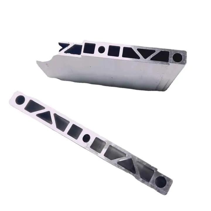
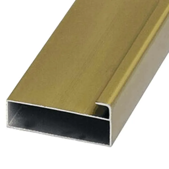
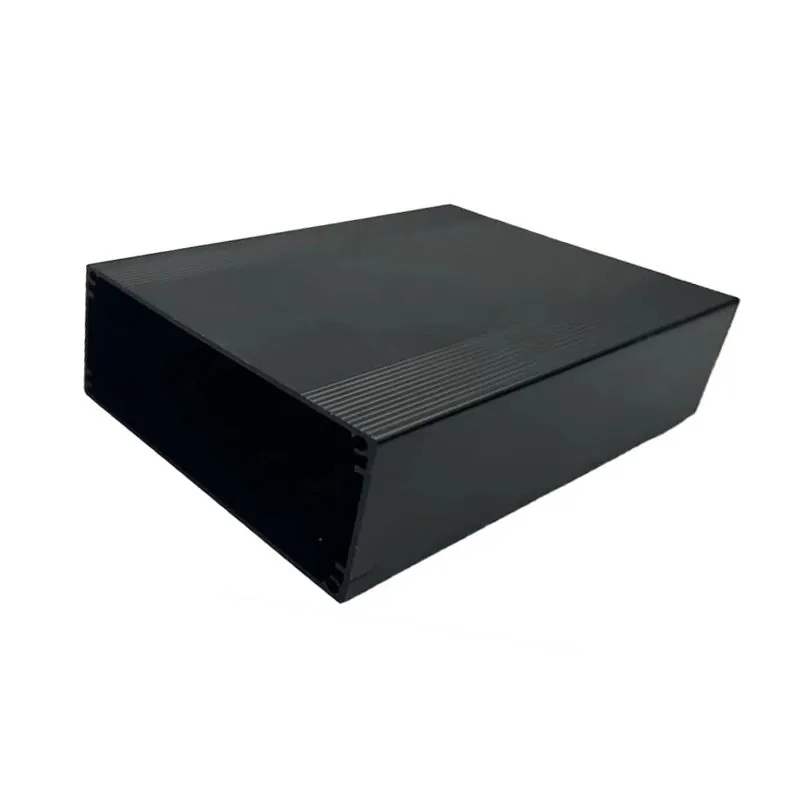
In one aluminium extrusion system I worked on, replacing a slim shaft with a thicker tube and adding a center support halved the twist angle under load. This fixed alignment issues and boosted machine stability.
What are the trends in torsional stiffness optimization?
As materials, manufacturing methods and simulation tools evolve, so do the ways engineers optimise torsional stiffness—and some newer approaches are quite interesting.
Current trends include topology/free‑form optimisation for torsional rigidity, meta‑material and adaptive‑stiffness structures, and integrated stiffness design from the start of product development.
Let me walk you through five key trends I see shaping how torsional stiffness is being optimised:
1. Topology and free‑form optimisation
- Uses algorithms to shape parts for best stiffness-to-weight ratio
- Popular in aerospace and automotive
- Saves material, cuts cost
2. Meta-materials and adaptive stiffness
- Smart materials change stiffness as needed
- Useful for dynamic loads
- Still emerging in industrial use
3. Early integration into design
- Include stiffness targets from day one
- Avoids costly late-stage redesigns
- Enables performance-focused development
4. Lightweighting without stiffness loss
- Use thin-walled, ribbed sections
- Combine different alloys or composites
- Critical in transport and renewable sectors
5. Simulation-driven optimization
- CAD + FEA for real-world predictions
- Reduce trial-and-error
- Supports better collaboration
Trends Overview
| Trend | Impact |
|---|---|
| Topology optimization | Best use of space and material |
| Meta-materials | Responsive, smart stiffness |
| Early stiffness planning | Avoid late-stage issues |
| Lightweighting strategies | Balance strength and efficiency |
| Simulation-driven design | Predict and optimize early |
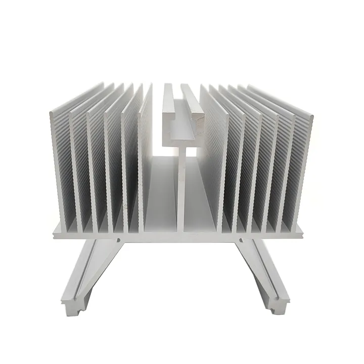
In aluminium profile design, we now combine wall thickness changes, ribs, and box shapes to boost torsional stiffness. These small choices make a big difference when multiplied over many meters of structure or hundreds of machines.
Conclusion
Torsional stiffness is the measure of a component’s resistance to twisting under torque. It matters because it impacts alignment, performance, durability and safety in design. You can measure it via torque/angle tests or derived from material and geometry using (K_t = G\,J/L). To improve torsional stiffness you can adjust geometry, use stiffer materials, optimise joints and use simulation tools. The latest trends push optimisation further with topology tools, adaptive materials, lightweighting strategies and integrating stiffness into the early design process.