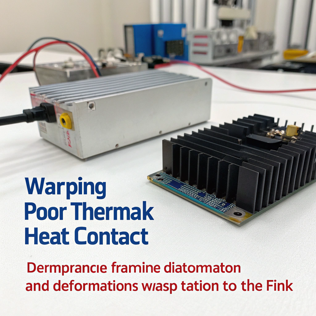
I once managed an OEM project where heat sink warping led to poor thermal contact. The delay and cost overrun taught me how crucial machining tolerances are.
Accurate machining tolerances for heat sinks ensure reliable thermal contact, correct assembly, and long-term performance in OEM systems.
In this article, I will walk through the most common tolerance questions for OEM heat sinks: what tolerances are standard, how tight specs affect cost, which processes ensure precision, and whether custom OEM parts need special requirements.
What tolerances are typical for OEM heat sinks?
Heat sink effectiveness often depends not only on material or design but also on the tolerances during production. Poor dimensional control leads to misalignment, poor thermal contact, and failed assemblies.
Standard tolerance ranges for OEM heat sinks reflect extrusion precision, machining allowances, and assembly requirements.

When planning OEM heat sinks, I focus on several critical dimensions:
Key Tolerance Types
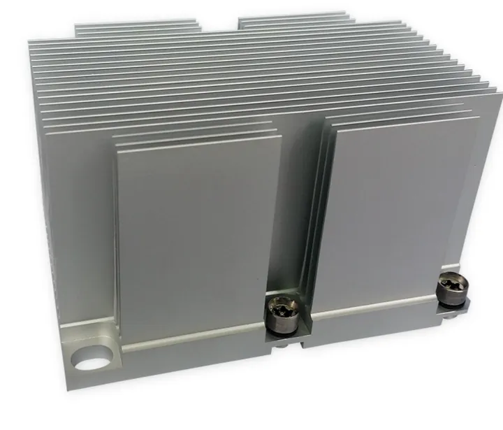
- Base flatness: This is vital for thermal contact. Typical flatness for machined bases ranges around ±0.03 mm per 100 mm.
- Hole positions: For mounting or interface alignment, tolerances are often between ±0.05 and ±0.1 mm.
- Overall dimensions: Total length, width, and height tolerances vary depending on the part size but usually fall between ±0.1 and ±0.3 mm.
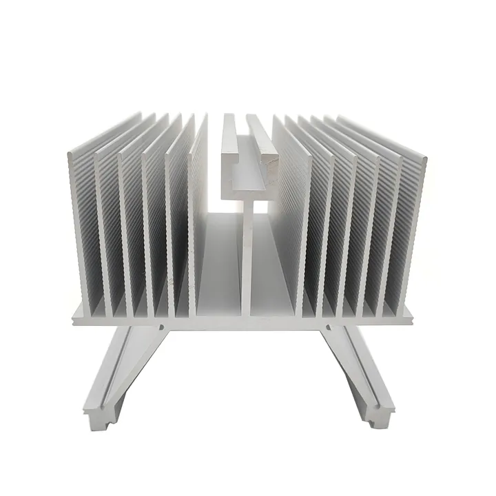
- Fin spacing and thickness: For dense fin structures, tolerances need to be tighter—often ±0.05 mm or less.
- Surface roughness: For thermal pads or interface pastes, an Ra of less than 0.8 µm is often required.
These values represent a balance between precision and manufacturability. Below is a table summarizing typical tolerances:
| Feature | Typical Tolerance | Purpose |
|---|---|---|
| Base flatness | ±0.03 mm / 100 mm | Ensures good thermal contact |
| Hole location | ±0.05 – ±0.1 mm | Precise mounting alignment |
| Overall length/width | ±0.1 – ±0.3 mm | General structural fit |
| Fin spacing/thickness | ±0.05 mm or tighter | Maintains airflow and surface area |
| Surface roughness (Ra) | ≤ 0.8 µm | Reduces thermal resistance |
These tolerances form a starting point. Depending on the heat sink's role—passive radiator or integrated thermal-mechanical part—you can adjust them. In power modules, I typically tighten base flatness and surface finish, while being more lenient on exterior dimensions.
It’s important to align tolerance settings with actual performance needs. Over-specification raises costs unnecessarily, while under-specification causes technical failures.
How do tighter tolerances affect cost?
In OEM projects, specifying tighter tolerances seems like a guarantee for better quality. But in reality, every micron added to precision can multiply production costs and complexity.
Tighter machining tolerances for heat sinks tend to increase manufacturing cost, lead time, and inspection burden — so they must be justified by performance or assembly needs.
Here’s how tighter tolerances influence the bottom line:
Increased Machining Complexity
To achieve a flatness of ±0.02 mm instead of ±0.1 mm, standard milling may not be sufficient. You might need precision fly-cutting, grinding, or lapping. These steps are slower and more resource-intensive.
The same goes for hole locations. To meet ±0.05 mm tolerance, a CNC process with high-end calibration is required. It’s not just about cutting—it’s about holding position, thermal drift compensation, and machine stability.
More Scrap and Rejects
Tighter specs increase the likelihood of failure during inspection. Even small misalignments, tool wear, or slight material distortion can lead to rejection. As tolerances shrink, quality control becomes more stringent and time-consuming.
Cost Comparison Table
| Tolerance Range | Expected Cost Impact | Recommended Use Case |
|---|---|---|
| Standard (±0.1 mm base) | Base cost | General cooling, less precise assemblies |
| Medium (±0.05 mm base) | +20–30% increase | Moderate precision, limited interface area |
| Tight (±0.02 mm base) | +40–100% increase | Direct chip contact, high-performance zones |
From my experience, specifying tight tolerances everywhere leads to ballooning costs with little performance benefit. I recommend applying tight tolerances only on functional surfaces—like heat sink bases or mechanical mating points—and relaxing the rest.
Impact on Lead Time
Tighter tolerances also extend delivery time. Manufacturing takes longer, inspection becomes more involved, and rework cycles increase. For OEM clients with tight production schedules, this delay can create downstream issues.
To manage this, I use a balanced tolerance map—tight where it counts, flexible elsewhere. It optimizes cost, delivery, and performance.
Which processes ensure precision machining?
Achieving tight tolerances for heat sinks doesn’t happen by chance. It requires specific machining methods, tooling control, and inspection techniques.
Processes like CNC milling, jigged fixturing, surface grinding, and precision inspection enable consistent, high-tolerance machining for heat sinks.

When I coordinate precision heat sink production, I focus on these methods:
CNC Milling
Computer-controlled milling allows extremely precise control over depth, shape, and position. It’s used for surfacing bases, drilling mounting holes, and shaping custom profiles. Modern 3-axis and 5-axis machines allow tolerance control down to microns.
Fixturing and Datum Setup
Even the best CNC won’t hold tolerance without correct fixturing. Fixtures ensure the workpiece remains stable and correctly referenced. For heat sinks, I often define base planes or pin locations as datums in technical drawings.
Surface Finishing Techniques
To reach surface flatness and roughness levels required for direct thermal contact, finishing processes like fly-cutting or surface grinding are used. In extreme precision jobs, lapping or polishing may be needed to reach Ra ≤ 0.4 µm.
Quality Control Tools
Precision metrology equipment—such as coordinate measuring machines (CMMs), laser scanners, or profilometers—confirms the product meets specs. On one OEM project, we rejected an entire batch because flatness was off by 0.04 mm, even though the part visually looked perfect.
Post-Processing Considerations
Post-machining steps like anodizing or powder coating can change part dimensions. I always account for coating thickness in tolerance stacks and check if the finish affects surface flatness.
These practices collectively form a production system where tolerances are not only specified, but reliably achieved. For OEM clients, I recommend working with manufacturers that document their process control and measurement systems.
Are special tolerances required for custom OEM parts?
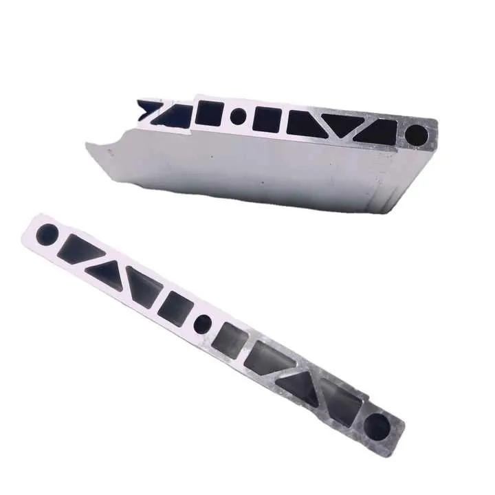
Custom OEM heat sinks often go beyond standard extrusion. They might integrate multiple parts, serve as structural elements, or need exact fitment. This makes tolerances more critical.
Yes, special tolerances are often required for custom OEM heat sinks when the design interface, thermal contact, mechanical mounting or assembly feature demands are beyond standard use.

When Special Tolerances Are Necessary
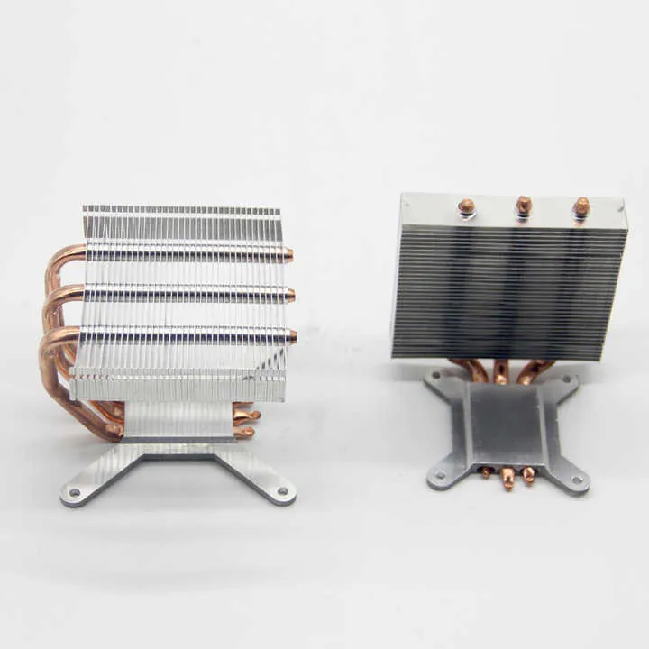
- Device-Mating Surfaces: For heat sinks mounted directly onto chips or modules, flatness often must be within ±0.02 mm. The thinner the thermal interface material, the tighter the flatness needed.
- Precision Mounting Systems: When the heat sink is part of a larger assembly, hole locations must align with other components. Position tolerances of ±0.05 mm may be necessary.
- Moving or Dynamic Assemblies: For devices with vibration, movement, or shock exposure, geometric stability becomes crucial. Parallelism and perpendicularity tolerances come into play.
- Embedded Features: If your heat sink includes coolant channels, sensor slots, or embedded inserts, those features need specific tolerance control to function properly.
Tolerance Planning for Custom Parts
When designing a custom part, I do a tolerance breakdown with the engineering team. We classify every feature:
- Critical (tight tolerance): mating base, assembly holes
- Functional (moderate): interface pockets, screw bosses
- Non-critical (standard): outside edges, non-contact fins
Then we specify tolerances only where needed. For instance:
| Feature Type | Suggested Tolerance |
|---|---|
| Device-mating base | Flatness ±0.02 mm |
| Mounting hole position | ±0.05 mm |
| Surface finish (Ra) | ≤ 0.4 µm |
| Alignment pin locations | ±0.03 mm |
| Outer profile | ±0.2 mm |
This method ensures that we control the important features while keeping cost and complexity down.
Matching Tolerances to Function
For OEM systems, every millimetre of stack-up matters. If your heat sink base is off, your chip overheats. If your holes don’t align, your whole assembly is delayed.
I always review the final assembly drawing and cross-check tolerance compatibility. Are the parts that must touch actually aligned? Are hole callouts shared across components?
These checks prevent headaches during assembly and testing.
Conclusion
In OEM heat sink projects I always emphasise: define tolerances based on function, not arbitrarily tight; understand how tighter tolerances affect cost; ensure the machining processes and supplier capabilities support the precision you ask for; and treat custom parts with special tolerances only where needed. A well‑specified tolerance plan saves cost, ensures thermal performance and avoids assembly headaches.