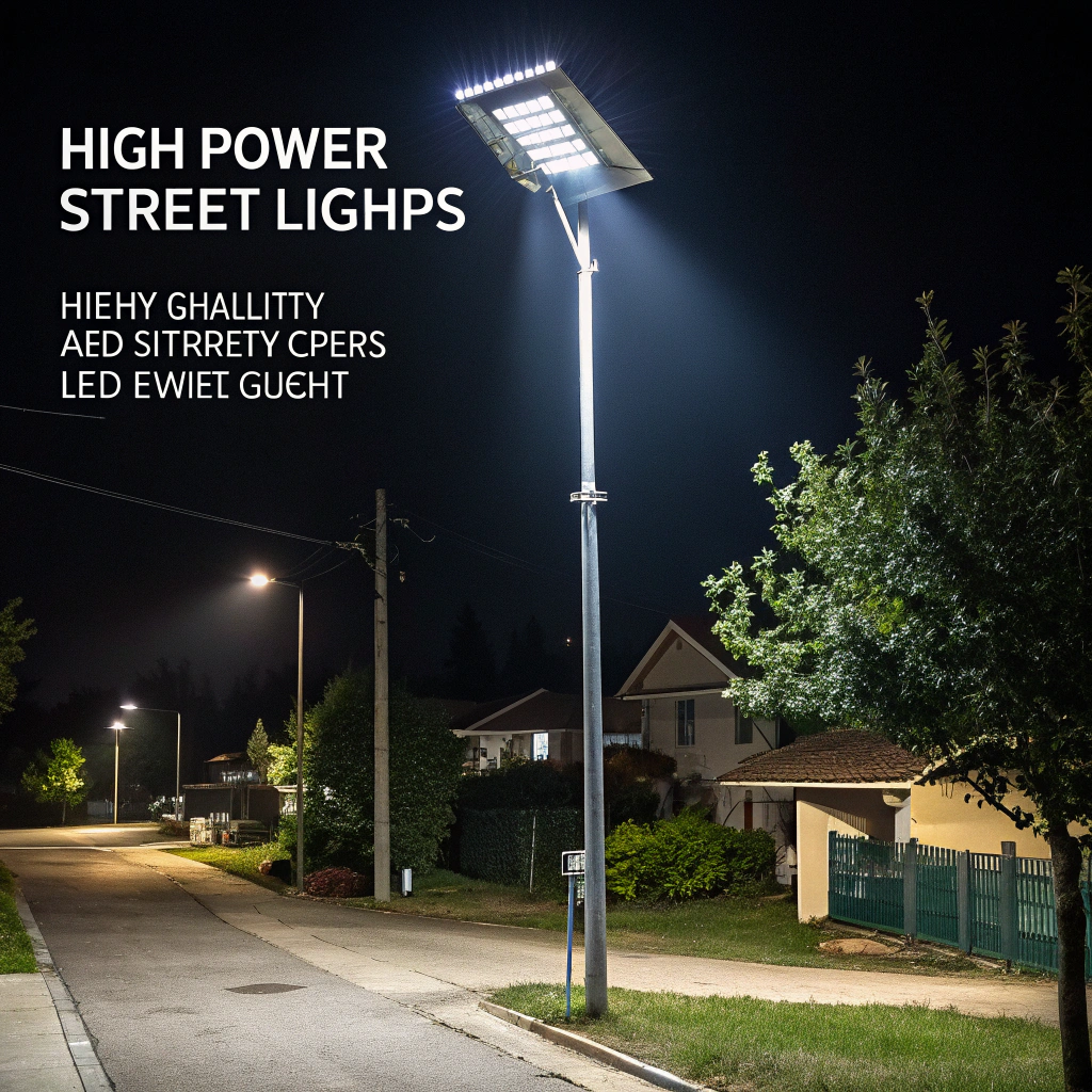
A few years ago, I worked on a high-power LED streetlight project. The LED chips were high-quality, and the drivers were stable, but the lights kept failing. The issue? The heat sinks couldn’t handle the power load.
For high-power LED systems, heat sink performance directly impacts brightness stability, lifespan, and system safety.
Now, whenever I design thermal solutions for LED lighting, I start by analyzing the heat flow path, choosing materials, optimizing geometry, and considering whether active cooling is necessary.
What enhances cooling for high-power LEDs?
LEDs convert most of their electrical energy into heat—not light. If you don’t remove that heat quickly, LED performance drops and degradation speeds up.
Better LED cooling is achieved by increasing surface area, improving thermal conduction, reducing resistance, and optimizing airflow.

From my engineering experience, here are the most effective cooling strategies:
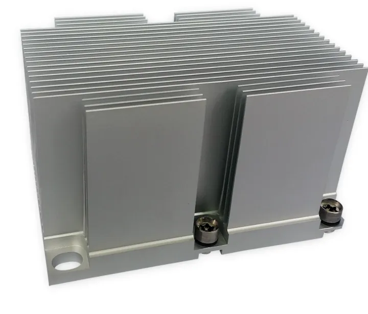
Increase surface area
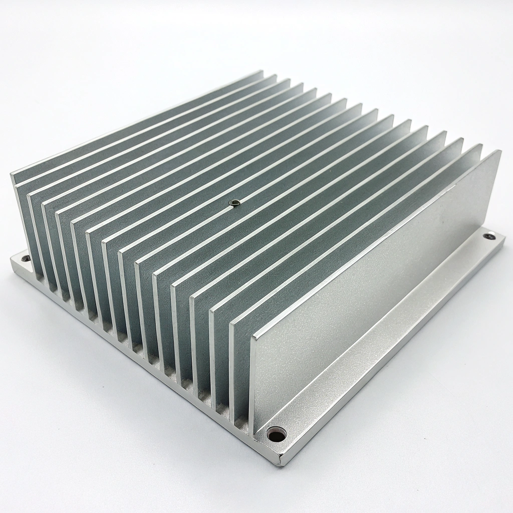
A larger surface area increases the rate of heat dissipation through convection. Using tall, narrow, and well-spaced fins increases the contact area between the heat sink and ambient air.
Lower thermal resistance
The lower the thermal resistance (RθJA), the better. This value describes how efficiently heat travels from the LED junction to the ambient. I always aim to design systems with thermal resistance below manufacturer-specified limits.
Improve thermal interface
Even microscopic air gaps between the LED module and the heat sink base add resistance. I recommend thermal pads, grease, or adhesives to fill gaps and create a smooth thermal path.
Manage airflow
If convection is passive, fin spacing must avoid airflow blockage. If forced air is used, airflow direction and distribution must match the fin layout.
Consider environmental temperature
Ambient temperature affects thermal dissipation. An LED system installed outdoors in hot climates needs significantly more cooling headroom than one in a controlled indoor space.
Here's a summary table of these factors:
| Cooling Factor | Function | Engineering Action |
|---|---|---|
| Surface Area | Boosts heat dissipation via air | Increase fin height, spacing, coverage |
| Thermal Interface | Reduces conduction loss | Apply thermal pads or pastes properly |
| Material Conductivity | Enhances internal heat flow | Use aluminium alloys or copper inserts |
| Airflow Management | Increases heat removal rate | Optimize geometry for airflow patterns |
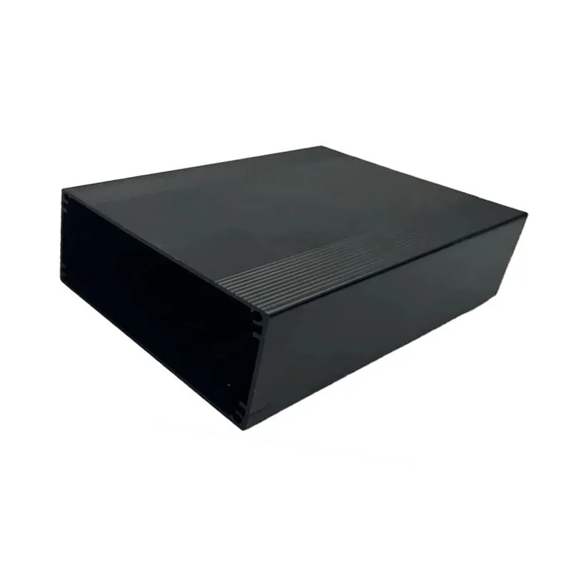
| Enclosure Design | Affects ambient heat build-up | Design for ventilation or forced cooling |
Over 80% of thermal failures in LED lighting projects I've seen stem from poor cooling design. That's why I always start with a full thermal map and resistance budget before finalizing the mechanical design.
How does material choice affect LED heat sinks?
Some clients choose low-cost aluminum alloys to save money—only to find out that their LEDs run hot and fail early, even though the heat sink looks big enough.
The material of a heat sink determines its ability to conduct heat from the LED chip to ambient, balancing thermal performance, weight, cost, and ease of manufacturing.
Thermal conductivity, measured in W/m·K, is the key metric here. The higher it is, the better the material moves heat.
Common materials
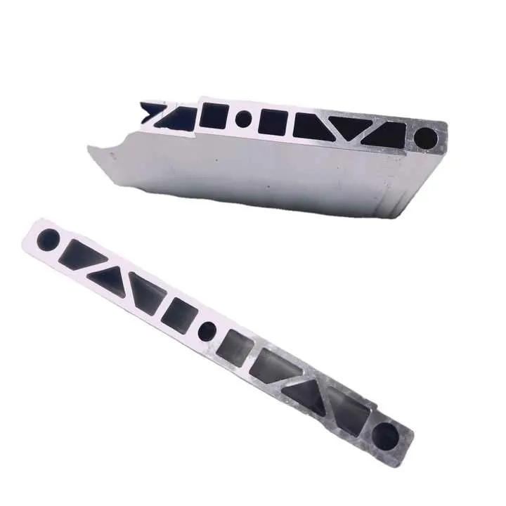
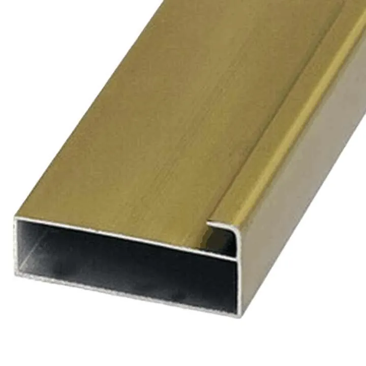
Aluminum is the standard in LED heat sinks—especially alloys like 6063 and 6061. These alloys are lightweight, affordable, and easy to extrude into complex shapes.
Copper conducts heat much better than aluminum, but it’s heavy, expensive, and hard to machine. I sometimes use copper inserts or bases in very high-power LED modules.
Material comparison:
| Material | Thermal Conductivity (W/m·K) | Weight | Cost | Common Use Case |
|---|---|---|---|---|
| Copper | ~385 | Heavy | High | COB bases, high-end spotlights |
| 6063 Alu | ~200 | Light | Medium | Extruded fins, LED luminaires |
| 6061 Alu | ~170 | Light | Medium | Mountable heat sinks, structural roles |
Surface finish compatibility
Aluminum alloys work well with anodizing and powder coating, which improves corrosion resistance and surface emissivity. These finishes also help boost radiation cooling slightly.
Interface continuity
Heat must travel through multiple layers—chip, PCB, solder, thermal pad, heat sink base, fins. A weak material at any stage slows the whole system down. I always ensure thermal conductivity is consistent across all layers.
In summary, choosing the right material isn’t just about conductivity. You have to consider cost, manufacturability, finish options, and system integration. For most LED lighting systems, 6063 aluminum remains the top choice.
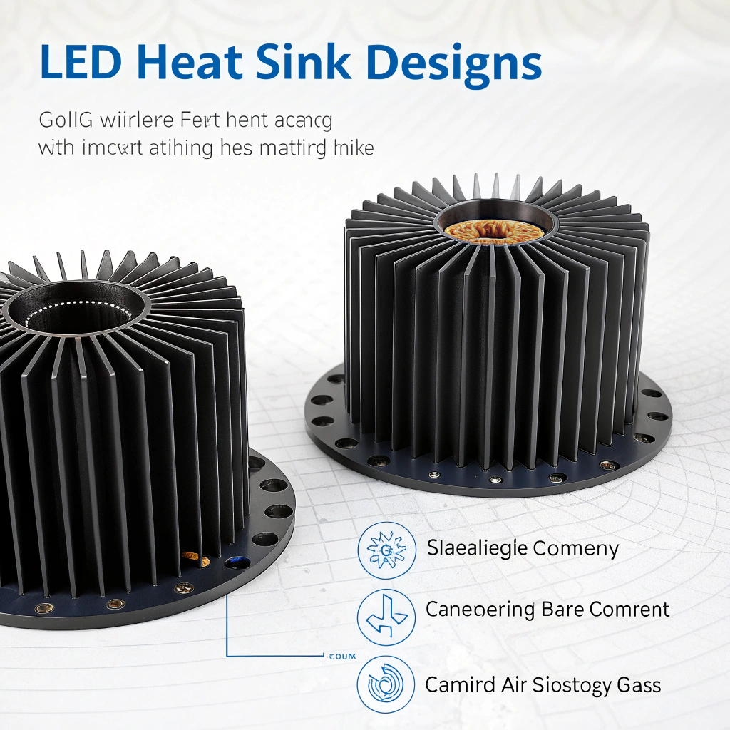
Which designs optimize LED thermal flow?
Material matters—but design matters more. A poorly designed heat sink made of copper can perform worse than a well-optimized aluminum one.
Optimal LED heat sink designs guide heat away from the source and into air efficiently, using engineered fin geometry, spacing, orientation, and base design.
Start with the base
The LED chip is a small, intense heat source. You need a thick, flat, thermally conductive base to spread the heat evenly before it reaches the fins. I usually recommend a base at least 3 mm thick.
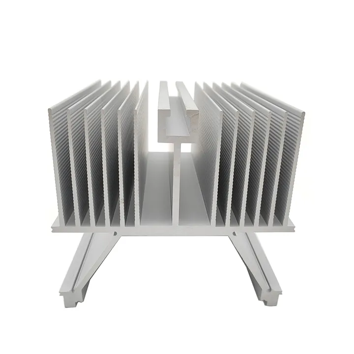
Fin design rules
| Parameter | Recommended Range | Purpose |
|---|---|---|
| Fin Height | 20–60 mm | Increases surface area |
| Fin Spacing | 3–5 mm | Prevents air stagnation, enables flow |
| Fin Thickness | 1–2 mm | Structural strength + density |
| Orientation | Vertical best | Aligns with natural convection |
Star-shaped or pin-fin heat sinks work well for omnidirectional air movement. For fixtures like floodlights, linear fins that match the lamp’s orientation are better.
Match the environment
Fixture position affects airflow. Ceiling-mounted LEDs need different heat sink layouts than wall-mounted floodlights. I always adjust fin orientation to fit installation geometry.
Simulation helps
I always run thermal simulations using CFD tools during early design. This helps identify airflow choke points and hotspot zones before prototyping.
Smart design lets you lower junction temperatures without increasing size or cost—making it the most efficient way to boost LED longevity.
Are active coolers needed for stronger LEDs?
As LED power increases, passive cooling reaches its limit. You can’t rely on just aluminum and airflow if your LEDs are pushing 100W or more.
Active cooling (e.g., fans or heat pipes) is required when LED power density exceeds what passive systems can dissipate within safe temperature ranges.
When passive works
For LEDs below 20W in open-air conditions, passive heat sinks are enough. Even up to 50W is possible with optimized geometry, large fins, and good airflow.
When active is needed
- Power levels above 80–100W
- Confined spaces with poor airflow
- Fixtures sealed for waterproofing
- Environments with high ambient temperatures
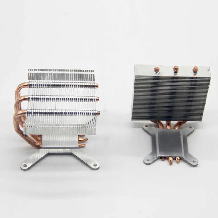
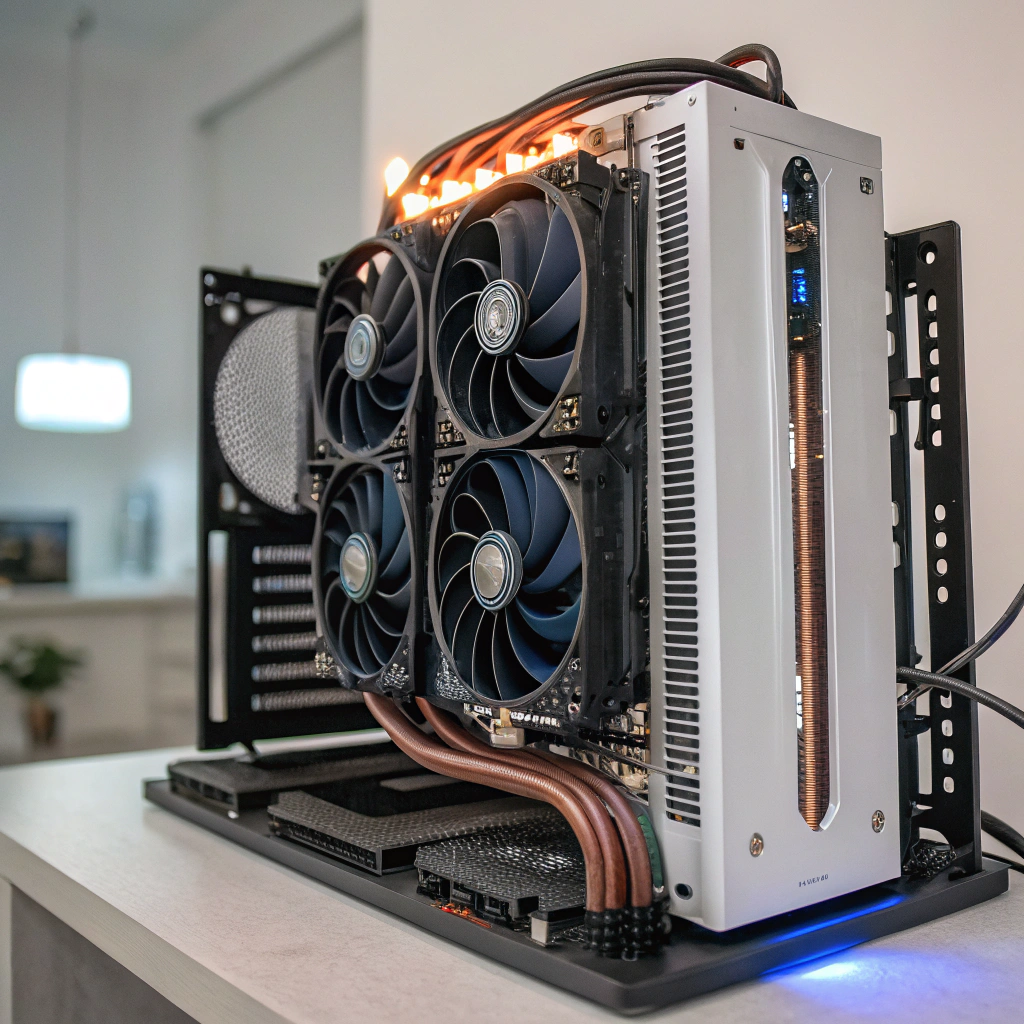
Active cooling options
- Fans: Add forced air to increase convection. Downsides are noise, dust, and moving parts.
- Heat pipes: Move heat from the LED base to remote fins.
- Vapor chambers: Spread heat across a wide base quickly.
- Liquid cooling: Rare, but used in large industrial or stage lighting setups.
Decision matrix
| Power Level | Environment | Cooling Recommendation |
|---|---|---|
| < 20W | Open air | Passive |
| 20–80W | Limited space | Enhanced passive or fan assist |
| > 100W | Enclosed/sealed | Heat pipes or active cooling |
My philosophy is always to start with passive cooling. I only move to active systems when space is too tight or performance requirements exceed passive limits.
Conclusion
In high-power LED projects, the heat sink isn’t just a mechanical part—it’s a core element of system design. I always begin with thermal targets, choose materials carefully, design the shape for the application, and run simulations to catch problems early. And when passive isn’t enough, I apply active cooling only where truly needed. Done right, your LEDs stay cool, efficient, and reliable for years.