
I’ve seen countless parts come back from machining only to fail inspection because the tolerance was wrong. That moment when you realise “this dimension is slightly off” can send shivers down the spine.
Tolerance in machining is the allowable deviation from a nominal dimension, size, or geometry that still lets a part function as intended.
Let’s dive in and understand how tolerance works, why it matters, how we apply unilateral vs bilateral tolerances, and what evolving standards are worth knowing.
Why Are Tolerance Types Important in Precision Machining?
Ever had two parts that looked identical but didn’t fit together? That usually means the tolerances weren’t properly specified or aligned.
Different tolerance types matter because they directly impact function, fit, cost and manufacturing feasibility.

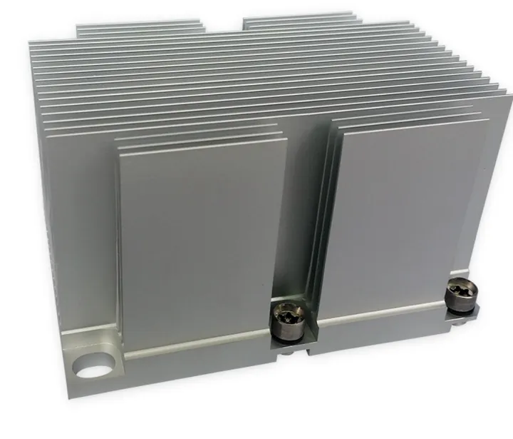
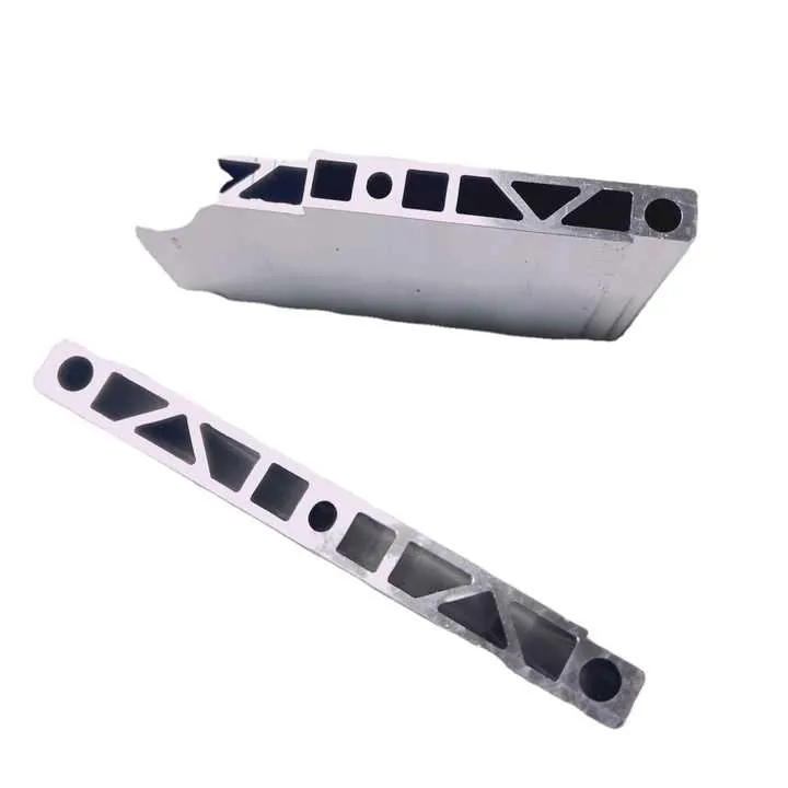
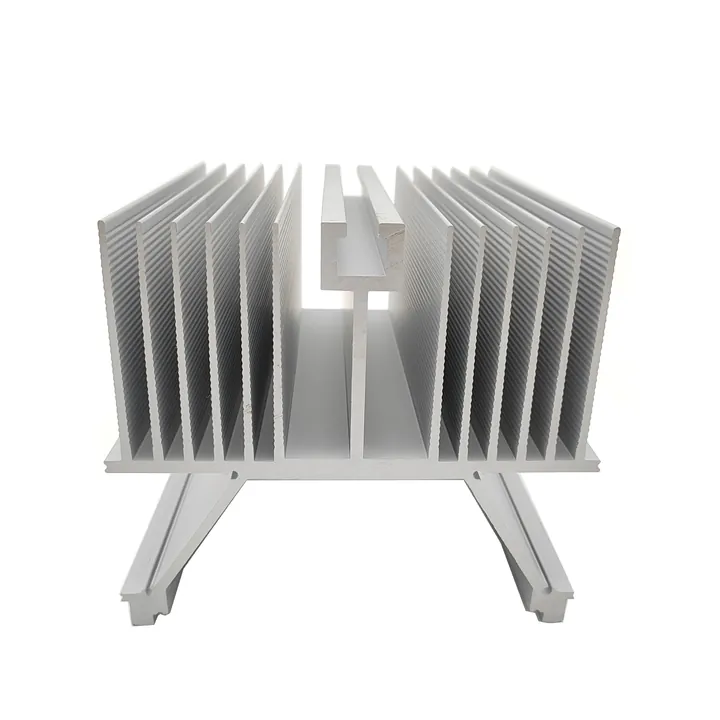
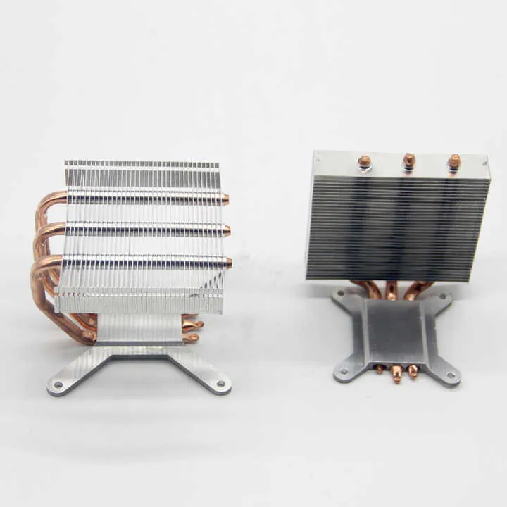
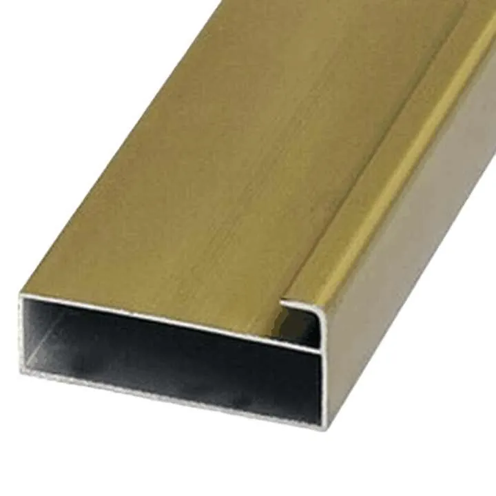
In precision machining (for example for your company’s aluminium profiles in construction or industrial use), tolerance types determine whether parts can be interchangeable, whether assemblies will run smoothly, and whether downstream customers will complain.
If the tolerance is too loose, the part might not function properly or may wear out faster. If it's too tight, it can increase manufacturing cost, cause delays, or make inspection harder.
Example scenarios from the field
- A solar panel frame extrusion that is 0.2 mm too wide may not fit into its bracket.
- A machined bracket with a too-tight pin hole may require reaming or won't assemble without force.
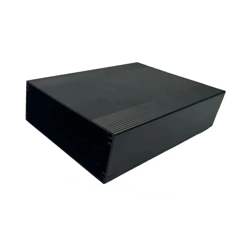
- A housing part for LED fixtures may rattle if inner tolerance is not controlled.
Here’s a simple table showing what tolerance ranges mean in real-world impact:
| Tolerance range | Typical application | Risk of being too loose/tight |
|---|---|---|
| ±0.5 mm | Structural parts, low-fit importance | May wobble, misalign |
| ±0.1 mm | Assembly parts, light machinery | Balanced fit and cost |
| ±0.01 mm | High precision components, bearing fits | High cost, sensitive to temperature/humidity |
When selecting tolerances, I always ask myself: what’s the part’s job? Then I work backwards to the tolerance that gets it done — reliably and affordably.
How to Apply Unilateral and Bilateral Tolerances?
Every time I read a technical drawing, I pause at the tolerance notation. That small symbol — ± or +0.1/−0.0 — can completely change how we make the part.
Unilateral tolerance allows deviation in one direction only. Bilateral tolerance allows deviation both above and below the nominal size.
Choosing between them depends on the functional needs of the part. I’ve seen too many drawings that used bilateral tolerances where only a one-sided deviation was acceptable.
When to use each
- Use unilateral when a hole must never be smaller than 20.00 mm, but can be a little larger.
- Use bilateral when a shaft must stay within a range around a central value, like ±0.05 mm.
- Use limit dimension when you want to write the max/min values directly: e.g., 9.90–10.10 mm.
How to decide what to apply
- Start from how the part functions.
- Ask: Is it more dangerous for the size to be too small or too large?
- Decide which side gets the "freedom."
- Match the tolerance type to the machining capability.
- Include clear notation in the technical drawing.
Practical example from aluminium extrusion
Imagine we’re producing an industrial profile for a customer in Germany. They require a 30.00 mm slot for sensor mounting:
- If the sensor must always fit (loose but not tight): we use 30.00 +0.20 / -0.00 mm.
- If the sensor needs to be tight but not crushed: we use 30.00 ±0.10 mm.
Common form examples
| Nominal Dimension | Unilateral Tolerance | Bilateral Tolerance |
|---|---|---|
| 10.00 mm | +0.10 / -0.00 mm | ±0.05 mm |
| 25.00 mm | +0.00 / -0.20 mm | ±0.10 mm |
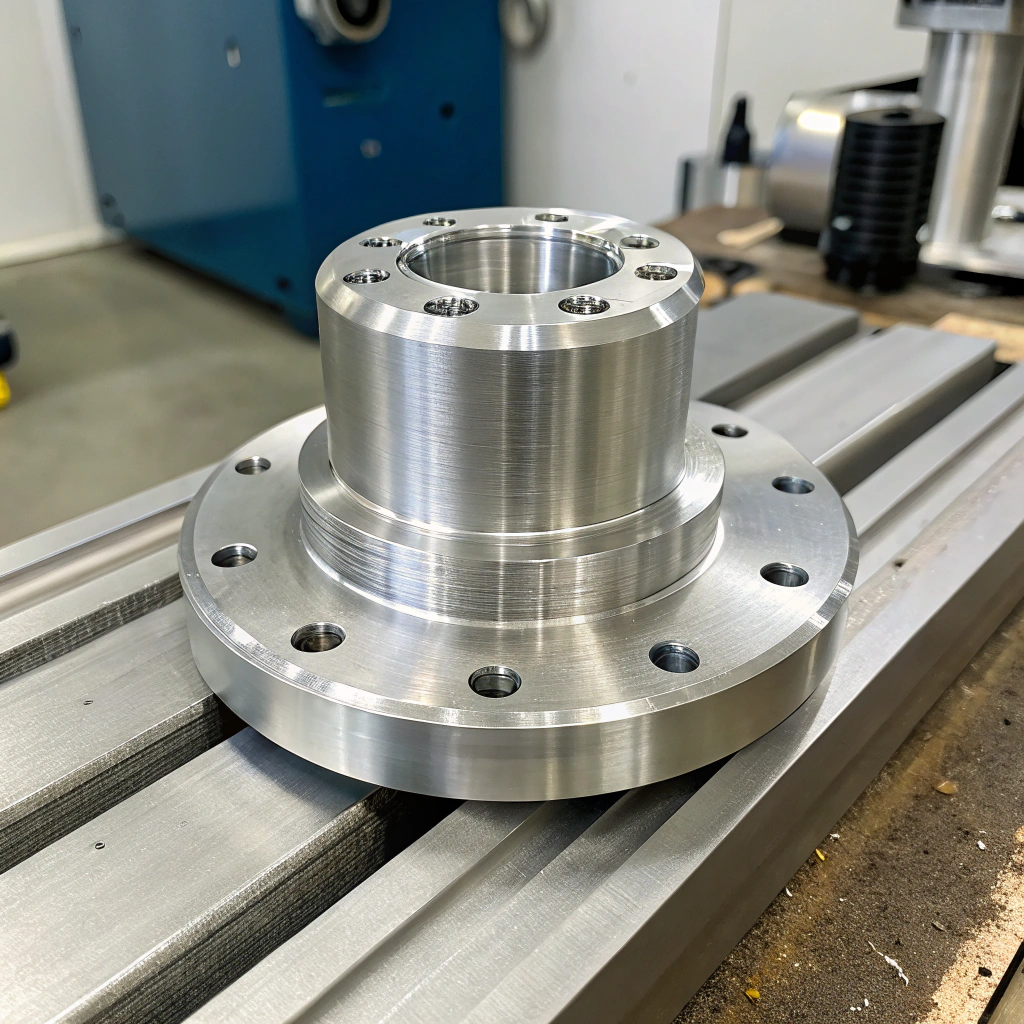
For aluminium CNC parts, especially for components like solar frame brackets, this precision ensures that the parts fit into their mounting points during field installation.
What Are the Evolving Standards in Tolerance Design?
In my early days, tolerances were just numbers you stuck next to a dimension. But today? They're a whole language — and the rules are changing.
New standards like ISO 2768 and ASME Y14.5 are shaping how we define, interpret, and inspect tolerances.

With global supply chains and tighter QA expectations, we can't afford to miscommunicate tolerances. These standards make expectations clear across borders.
Key standards to know
| Standard | What it covers | Why it matters |
|---|---|---|
| ISO 2768 | General tolerances for size and geometry | Common in Europe/Asia; avoids clutter in drawings |
| ASME Y14.5 | Geometric Dimensioning & Tolerancing (GD&T) | Clear feature control, vital for high precision |
| BS 8888 | UK standard aligned with ISO | Useful when working with UK or European partners |
How they impact production
- ISO 2768 allows us to apply default tolerances to whole drawings, simplifying the document and speeding up quoting.
- GD&T (ASME Y14.5) helps define how flat, straight, or concentric a feature must be — not just how "big."
- Modern standards also support 3D model-based definitions (MBD), where tolerances live inside the CAD file.
Trends I follow closely
- Tighter global integration: With clients from the Middle East to North America, a shared standard avoids errors.
- 3D annotated models: We're increasingly seeing STEP files with built-in GD&T data.
- Sustainability awareness: Some clients now ask if tight tolerances can be relaxed to reduce machining energy or scrap.
When working with construction extrusion for UAE clients or CNC‑finished lighting profiles for EU markets, I ensure our drawings mention ISO 2768-m or include GD&T for critical fits. That helps everyone — from machinist to QC — stay aligned.
Conclusion
Tolerance in machining is the allowable variation from the nominal size that still allows a part to function. Whether unilateral or bilateral, or defined under ISO or ASME rules, proper tolerance use affects everything from fit to cost. In my work with aluminium extrusion and CNC finishing, applying the right tolerance ensures our parts perform — wherever in the world they’re used.